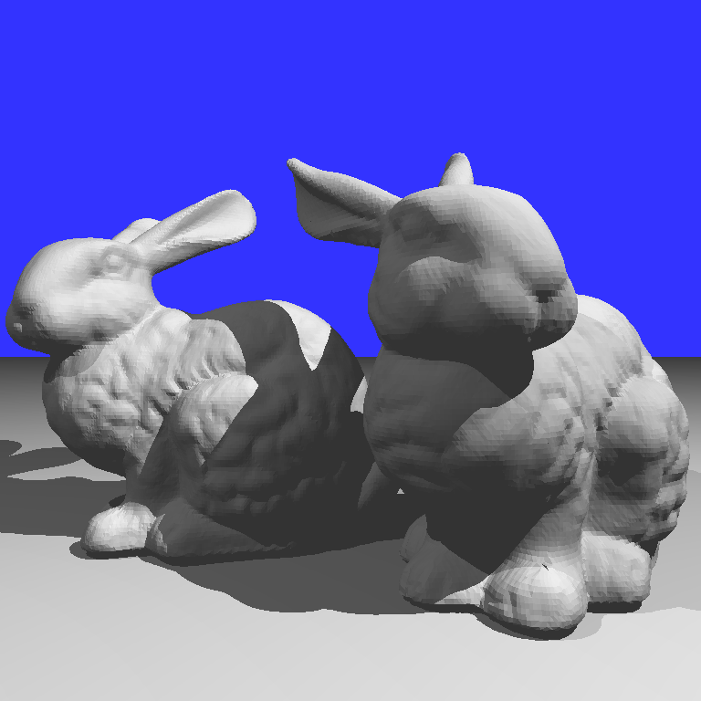
1. Basic Ray Tracer
In this project, a basic Whitted style ray tracer is implemented in processing. Currently, only diffuse model and hard shadow were rendered, and more effects would be integrated into a distributed ray tracer soon in the future.
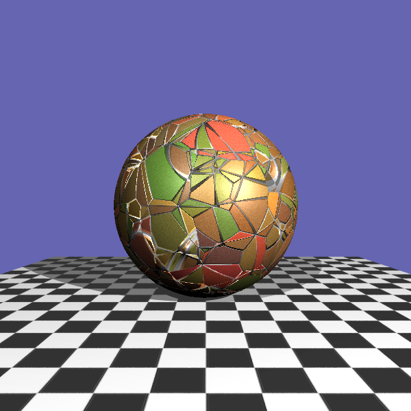
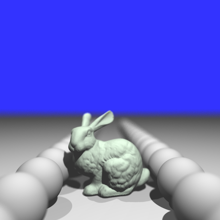
To accelerate the process of ray tracing, I used kd-Tree to store the primitives, with which I obtained an acceleration of around 60x times when rendering the Stanford Bunny (69k triangles).
To accelerate the process of ray tracing, I used kd-Tree to store the primitives, with which I obtained an acceleration of around 60x times when rendering the Stanford Bunny (69k triangles).
Results
2. Distributed Ray Tracing
Although Whitted style ray tracing can produce effect such as shadow, diffuse shading, etc. But it's hard for it to produce effects like soft shadow due to the fact that it shoots only one ray for each pixel. So in this project, I implemented the distributed ray tracing algorithm, which produces four types of effects that the previous ray tracer couldn't achieve: anti-aliasing, soft shadow, motion blur and depth of field.
Anti-Aliasing
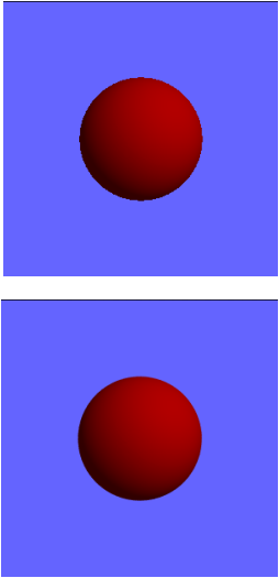
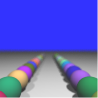
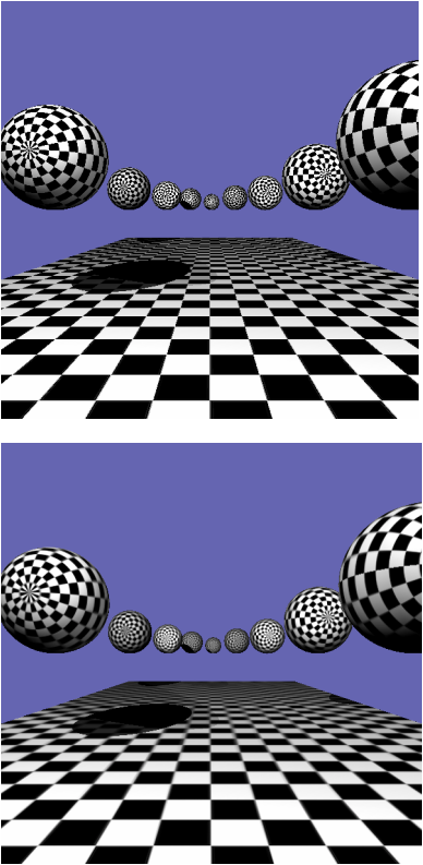
When there's only one ray casted from the eye to each pixel, it tends to create aliased image, where jagged silhouette can be seen. As is shown in the upper image on the left, you can see that the silhouette of the sphere is jagged. This is because the rays are discrete and they contain no information other than those at the center of the pixel.
To alleviate this problem, one can shoot multiple rays for each pixel, which each ray slighted perturbed within the range of that pixel and then average the color obtained from all rays to get the final color for the pixel. This would produce a much smoother silhouette as can be seen in the lower image on the left.
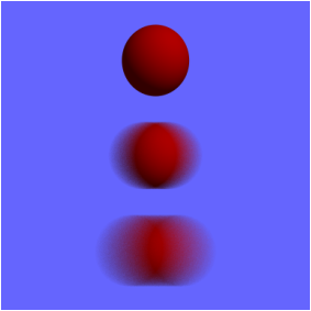
Motion Blur
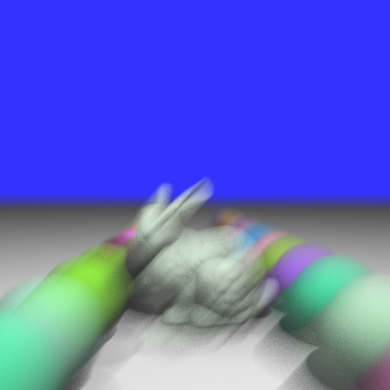
To achieve the effect of motion blur, the object need to be defined not only in space, but also in time. Assume that given a time t, we can get the geometry information of the object G(t) at that specific time, then the motion blur effect can be obtained by randomly picking a t for each of the rays and calculate the resulting color according to G(t).
In this project, the function G(t) is defined in a simplified way. We only allow sphere object to be motion blurred and we define the starting and ending point of a moving sphere. Then we can use t to get a linear interpolation between the starting and ending states of the sphere and do the ray tracing. The result is shown on the right.
Another method to create global motion blur is to move the camera instead of the object, which would case the entire scene to move.
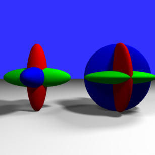
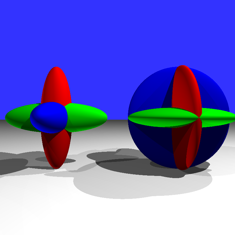
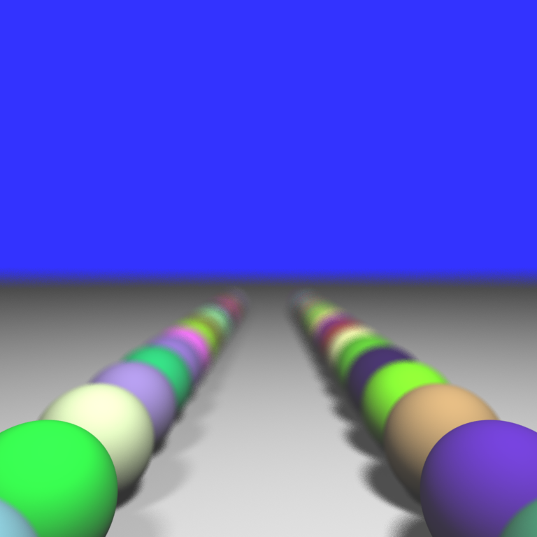
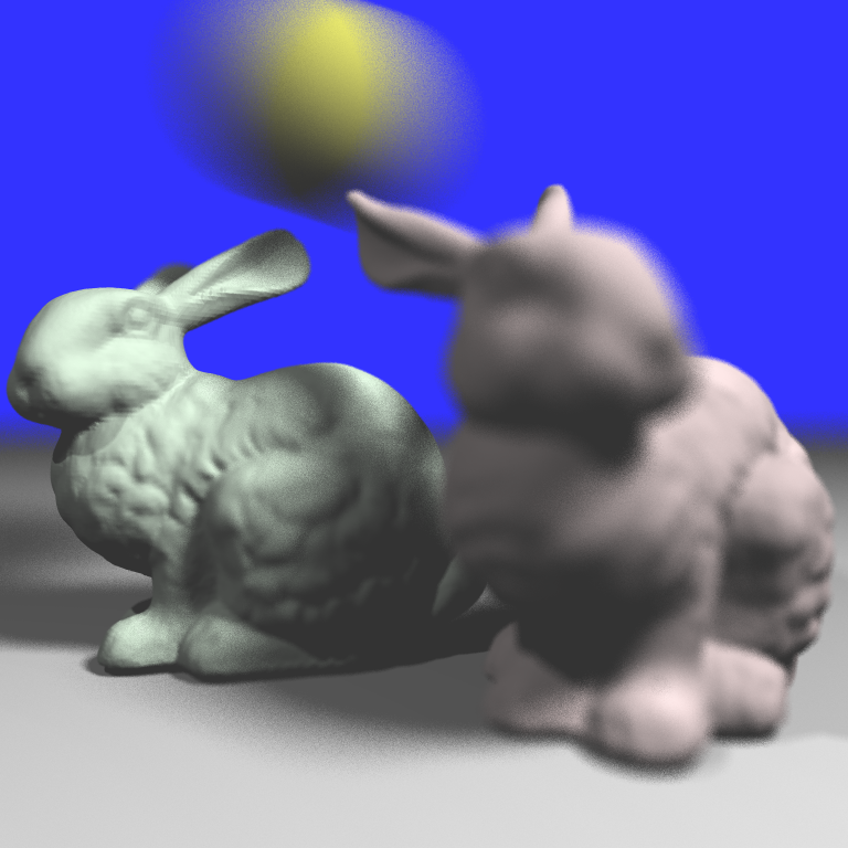
Soft Shadow
If we see around ourselves, we can see that most of the shadows of the objects have a blurred edge while in the previous rendering results we see very shape shadow edges. This is because we used point lights as light sources, which doesn't exist in real world. So, to produce a blurred shadow edge, or should we call it, a soft shadow, we can model the light source as an object with area or volume instead of a single point.
In this project, I used a disk light to produce the soft shadow effect. For each shadow ray, we cast it from the colliding point toward a randomly picked point on the disk light. Remember that we casts multiple rays for each pixel and average the color obtained. So for each pixel, we can have rays that are lighted by different points on the disk light and by averaging them we can achieve a nice soft shadow effect.
The result is shown on the right.
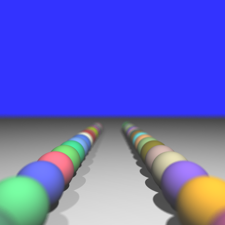
Depth of Field
In real life, we have a transparent, biconvex structure in our eyeballs called crystalline lens, which is used to focus the incoming light on the retina. This would cause the effect that we can see things more clearly when they're in focus while blurred when they're out of focus. But Whitted - style ray tracing couldn't achieve this effect because it uses a camera model that's more similar to a pinhole camera where all the lights goes through a small pinhole instead of a piece of lens.
In distributed ray tracing, the effect of depth of field is achieve by casting rays of the same pixel toward the same point in the space. To understand the method, we can imagine that each pixel is associated with a piece of lens with certain radius and eye rays are casted from the eye, go through the lens, and converge to a certain point in the scene. So if an object is at that certain point, the geometry information obtained from the rays for the same pixel would be the same ---- they collide with the mesh at the same point. If an object is near or far away from the point, then the colliding point for each ray would be different and we will see a blurred image. If we set a constant for the distance from the eye to the converging point of the lens and we gather the converging points for each pixel, we would get a plane or something similar to a plane. We call it the focal plane. By having different distances, we can move the focal plane forward or backward and produce image with different focuses.
Results
3. Image Based Texture
 Aliasing and anti-aliased image.
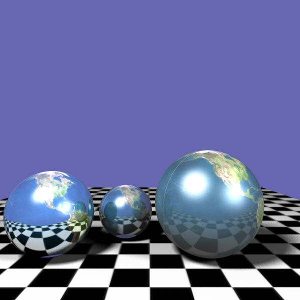
For this part, I added reflectance and texture into the renderer. The reflectance is just shooting another ray when the collided surface for the current ray is reflective and then combine the results afterwards.
For texture, I used the mipmap to generate an image pyramid for the texture. It has two main benefits. First, it makes the program faster cause when the object is far away, we can just look up the color in a low resolution texture. Second, when the object is so far away that within one pixel it covers a large area in the image texture, it's very likely that we will see aliasing in the image. In this case we would want to have a blurred version of the texture and then even for some pixel that covers a large area in the image texture space, within that area the colors are rather smooth.
For texture, I used the mipmap to generate an image pyramid for the texture. It has two main benefits. First, it makes the program faster cause when the object is far away, we can just look up the color in a low resolution texture. Second, when the object is so far away that within one pixel it covers a large area in the image texture, it's very likely that we will see aliasing in the image. In this case we would want to have a blurred version of the texture and then even for some pixel that covers a large area in the image texture space, within that area the colors are rather smooth.
Results
Procedural Texture
In image-based texture, we use an existing image as the texture for the object, while in procedural texture, this image is generated by the computer, which usually mimics the pattern of natural elements such as wood, marble, metal, stone, etc.
In this part, I added a 3d procedural part into the system and produced three types of procedural texturing effects: Wood, Marble and Stone.
The wood and marble texture are both based on Perlin noise.
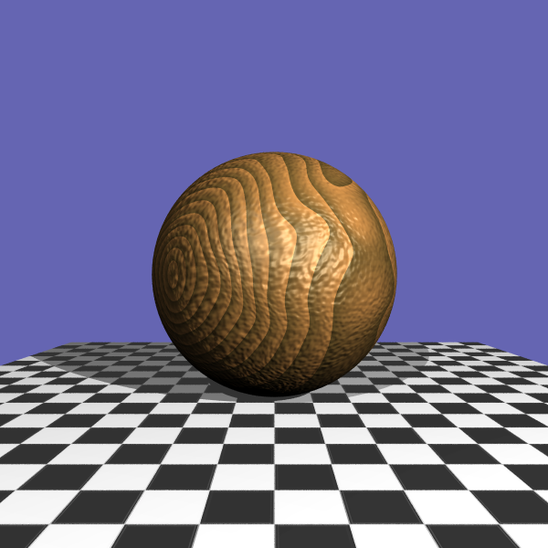
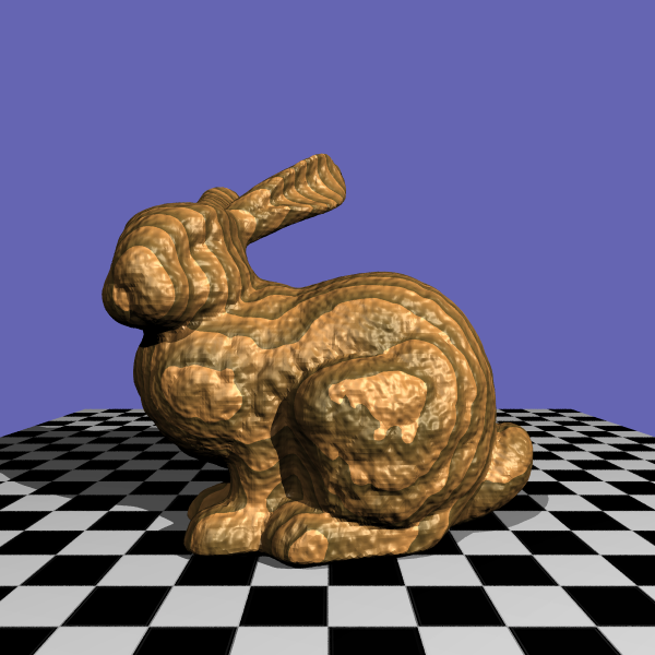
Wood texture is relatively simple, given a position x, y and z, we assign the light color or the dark color to this position according to the function: sqrt(y*y+z*z)/w, where w is the width for the tree rings. Then we can perturb the input x, y and z using the Perlin noise and we will get a slightly twisted wood texture. To add more randomness, I added another layer of Perlin noise on the result color to make the result look better.
In addition, I also added a bump mapping for the wood texture, which creates bumps on the surface of the object. I took the gradient of the Perlin noise and then perturb the surface normal using the gradient field.
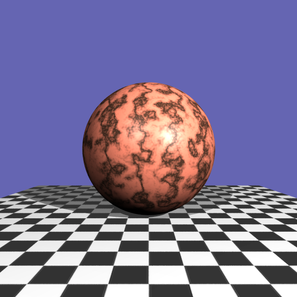
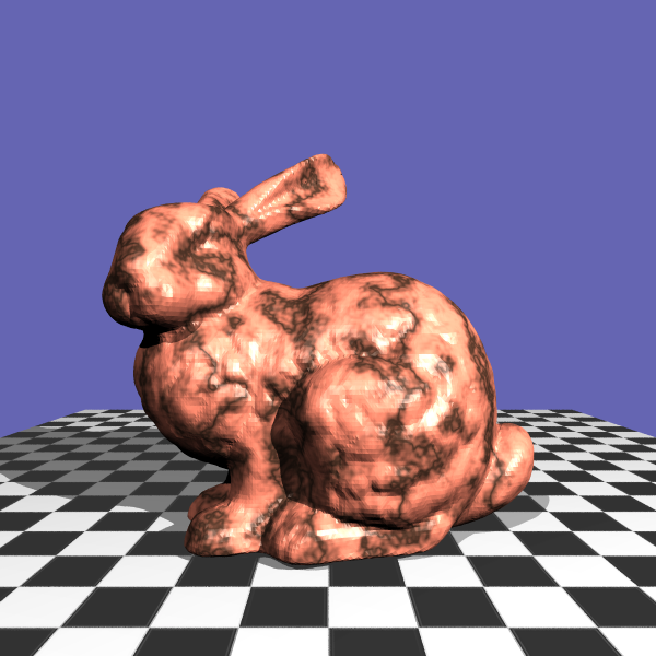
For the Marble texture, I used a turbulence function which recursively adds noise to the current noise value. Then the turbulence value is mapped to the color and create a twisted pattern.
For Stone texture, I used the Worley noise introduced by Steven Worley. The key idea of the algorithm is to create a bunch of points in the space and then for arbitrary point in the space we calculate its distance to the nth nearest point that we created before. This distance then is used to render the object, which creates a brick-like texture.
For this texture, I also created a bump mapping. But this time, I took the gradient from the distance field and only applied bump mapping to the connecting parts between tiles.
In this part, I added a 3d procedural part into the system and produced three types of procedural texturing effects: Wood, Marble and Stone.
The wood and marble texture are both based on Perlin noise.
Wood texture is relatively simple, given a position x, y and z, we assign the light color or the dark color to this position according to the function: sqrt(y*y+z*z)/w, where w is the width for the tree rings. Then we can perturb the input x, y and z using the Perlin noise and we will get a slightly twisted wood texture. To add more randomness, I added another layer of Perlin noise on the result color to make the result look better.
In addition, I also added a bump mapping for the wood texture, which creates bumps on the surface of the object. I took the gradient of the Perlin noise and then perturb the surface normal using the gradient field.
For the Marble texture, I used a turbulence function which recursively adds noise to the current noise value. Then the turbulence value is mapped to the color and create a twisted pattern.
For Stone texture, I used the Worley noise introduced by Steven Worley. The key idea of the algorithm is to create a bunch of points in the space and then for arbitrary point in the space we calculate its distance to the nth nearest point that we created before. This distance then is used to render the object, which creates a brick-like texture.
For this texture, I also created a bump mapping. But this time, I took the gradient from the distance field and only applied bump mapping to the connecting parts between tiles.